
Page 117 - Practical Power System and Protective Relays Commissioning
P. 117
Traditional and Electronic Current Transformers Theory Testing Chapter | 10 115
As an example for comparing the IEC and IEEE CT classes as follows:
5P20 (IEC)-C 100 (IEEE).
10.5.6 Linear Coupler Current Transformers
Linear coupler CTs have an air core and linear characteristics as shown in
Fig. 10.10. It produces a voltage that is proportional to the primary current
of the CT and can be used in busbar protection voltage differential relays.
The main advantage of these CTs is the avoidance of a saturated operating
region. When these CTs have a small air gap in an iron core, they are known
as called transactors.
10.6 CURRENT TRANSFORMERS CONNECTIONS
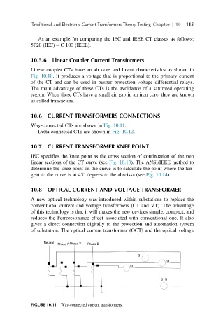
Way-connected CTs are shown in Fig. 10.11.
Delta-connected CTs are shown in Fig. 10.12.
10.7 CURRENT TRANSFORMER KNEE POINT
IEC specifies the knee point as the cross section of continuation of the two
linear sections of the CT curve (see Fig. 10.13). The ANSI/IEEE method to
determine the knee point on the curve is to calculate the point where the tan-
gent to the curve is at 45 degrees to the abscissa (see Fig. 10.14).
10.8 OPTICAL CURRENT AND VOLTAGE TRANSFORMER
A new optical technology was introduced within substations to replace the
conventional current and voltage transformers (CT and VT). The advantage
of this technology is that it will makes the new devices simple, compact, and
reduces the Ferroresonance effect associated with conventional one. It also
gives a direct connection digitally to the protection and automation system
of substation. The optical current transformer (OCT) and the optical voltage
FIGURE 10.11 Way-connected current transformers.