
Page 112 - Practical Power System and Protective Relays Commissioning
P. 112
110 Practical Power System and Protective Relays Commissioning
TABLE 10.2 Accuracy Versus Composite Error Calculations
Accuracy Class Composite (%) Error
5P 5
10P 10
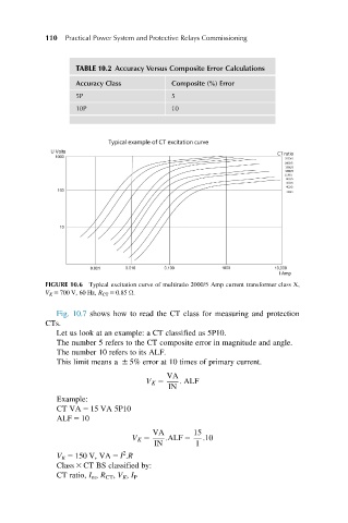
FIGURE 10.6 Typical excitation curve of multiratio 2000/5 Amp current transformer class X,
V K 5 700 V, 60 Hz, R CT 5 0.85 Ω.
Fig. 10.7 shows how to read the CT class for measuring and protection
CTs.
Let us look at an example: a CT classified as 5P10.
The number 5 refers to the CT composite error in magnitude and angle.
The number 10 refers to its ALF.
This limit means a 6 5% error at 10 times of primary current.
VA
V K 5 : ALF
IN
Example:
CT VA 5 15 VA 5P10
ALF 5 10
VA 15
V K 5 :ALF 5 :10
IN 1
2
V K 5 150 V, VA 5 I .R
Class 3 CT BS classified by:
CT ratio, I m , R CT , V K , I P