
Page 109 - Practical Power System and Protective Relays Commissioning
P. 109
Traditional and Electronic Current Transformers Theory Testing Chapter | 10 107
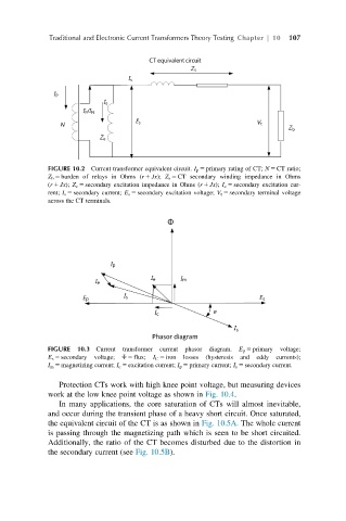
FIGURE 10.2 Current transformer equivalent circuit. I p 5 primary rating of CT; N 5 CT ratio;
Z b 5 burden of relays in Ohms (r 1 Jx); Z s 5 CT secondary winding impedance in Ohms
(r 1 Jx); Z e 5 secondary excitation impedance in Ohms (r 1 Jx); I e 5 secondary excitation cur-
rent; I s 5 secondary current; E s 5 secondary excitation voltage; V t 5 secondary terminal voltage
across the CT terminals.
FIGURE 10.3 Current transformer current phasor diagram. E p 5 primary voltage;
E s 5 secondary voltage; Φ 5 flux; I C 5 iron losses (hysteresis and eddy currents);
I m 5 magnetizing current; I e 5 excitation current; I p 5 primary current; I s 5 secondary current.
Protection CTs work with high knee point voltage, but measuring devices
work at the low knee point voltage as shown in Fig. 10.4.
In many applications, the core saturation of CTs will almost inevitable,
and occur during the transient phase of a heavy short circuit. Once saturated,
the equivalent circuit of the CT is as shown in Fig. 10.5A. The whole current
is passing through the magnetizing path which is seen to be short circuited.
Additionally, the ratio of the CT becomes disturbed due to the distortion in
the secondary current (see Fig. 10.5B).