
Page 110 - Practical Power System and Protective Relays Commissioning
P. 110
108 Practical Power System and Protective Relays Commissioning
FIGURE 10.4 Current transformer (CT) knee point voltage in measuring and protection CTs.
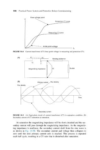
FIGURE 10.5 (A) Equivalent circuit of current transformer (CT) in saturation condition. (B)
Secondary current of CT distortion at saturation.
At saturation the magnetizing impedance will be short circuited and the sec-
ondary current will pass through the magnetizing impedance. As the magnetiz-
ing impedance is nonlinear, the secondary current draft from the sine wave is
as shown in Fig. 10.5B. The secondary current and voltage then collapses to
zero until the next primary current zero is reached. This process is repeated
each half cycle, resulting in a CT ratio that is disturbed after saturation.