
Page 111 - Practical Power System and Protective Relays Commissioning
P. 111
Traditional and Electronic Current Transformers Theory Testing Chapter | 10 109
10.4 CURRENT TRANSFORMER ACCURACY CLASSES
10.4.1 Metering Current Transformer Accuracy Classes
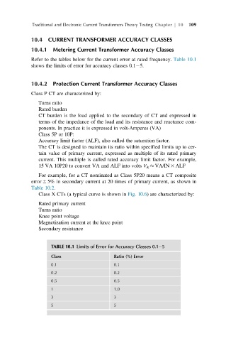
Refer to the tables below for the current error at rated frequency. Table 10.1
shows the limits of error for accuracy classes 0.1 5.
10.4.2 Protection Current Transformer Accuracy Classes
Class P CT are characterized by:
Turns ratio
Rated burden
CT burden is the load applied to the secondary of CT and expressed in
terms of the impedance of the load and its resistance and reactance com-
ponents. In practice it is expressed in volt-Amperes (VA)
Class 5P or 10P:
Accuracy limit factor (ALF), also called the saturation factor.
The CT is designed to maintain its ratio within specified limits up to cer-
tain value of primary current, expressed as multiple of its rated primary
current. This multiple is called rated accuracy limit factor. For example,
15 VA 10P20 to convert VA and ALF into volts V K VA/IN 3 ALF
For example, for a CT nominated as Class 5P20 means a CT composite
error 6 5% in secondary current at 20 times of primary current, as shown in
Table 10.2.
Class X CTs (a typical curve is shown in Fig. 10.6) are characterized by:
Rated primary current
Turns ratio
Knee point voltage
Magnetization current at the knee point
Secondary resistance
TABLE 10.1 Limits of Error for Accuracy Classes 0.1 5
Class Ratio (%) Error
0.1 0.1
0.2 0.2
0.5 0.5
1 1.0
3 3
5 5