
Page 130 - Practical Power System and Protective Relays Commissioning
P. 130
Voltage Transformers Chapter | 11 129
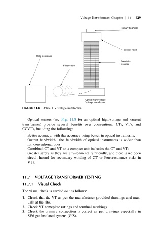
FIGURE 11.8 Optical HV voltage transformer.
Optical sensors (see Fig. 11.8 for an optical high-voltage and current
transformer) provide several benefits over conventional CTs, VTs, and
CCVTs, including the following:
Better accuracy, with the accuracy being better in optical instruments;
Output bandwidth—the bandwidth of optical instruments is wider than
for conventional ones;
Combined CT and VT as a compact unit includes the CT and VT;
Greater safety as they are environmentally friendly, and there is no open
circuit hazard for secondary winding of CT or Ferroresonance risks in
VTs.
11.7 VOLTAGE TRANSFORMER TESTING
11.7.1 Visual Check
The visual check is carried out as follows:
1. Check that the VT as per the manufacturer-provided drawings and man-
uals at the site.
2. Check VT nameplate ratings and terminal markings.
3. Check the primary connection is correct as per drawings especially in
SF6 gas insulated system (GIS).