
Page 131 - Practical Power System and Protective Relays Commissioning
P. 131
130 Practical Power System and Protective Relays Commissioning
4. Check secondary connections in the VT terminal box and in the local
control cubicle (LCC), the tightness and cross-sectional area of the
cables, and the color codes for phases and the ground cable.
5. Check the oil level in the outdoor PT and SF6 pressure in the SF6 GIS.
6. Check the MCB ratings of the VT secondary terminals in the LCC.
11.7.2 Insulation Resistance Test
This test is carried out at 5000 V DC as follows:
1. between primary and secondary;
2. between primary and earth; and
3. between secondary and earth.
Also, the voltage withstand test is performed at 2000 V AC 50 or 60 Hz
for 30 seconds between the primary and secondary windings of the VT.
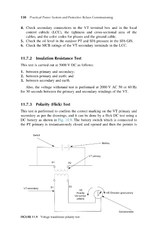
11.7.3 Polarity (Flick) Test
This test is performed to confirm the correct marking on the VT primary and
secondary as per the drawings, and it can be done by a flick DC test using a
DC battery as shown in Fig. 11.9. The battery switch which is connected to
the PT primary is instantaneously closed and opened and then the pointer is
FIGURE 11.9 Voltage transformer polarity test.