
Page 160 - Practical Power System and Protective Relays Commissioning
P. 160
160 Practical Power System and Protective Relays Commissioning
15.2.1 Discharging of a New Battery
Leave the battery to discharge in an external resistance (water resistance
may be used at site) for about 2 hours.
For example: The discharge current should start at 66 A for a 400 Ah
220 V battery for 200 ms, then 49 A for 2 hours.
15.3 BATTERY CHARGER
A battery charger consists of a rectifier circuit, power circuit, ripple monitor-
ing, control circuit, regulator circuit, and fault detection circuit. This charger
can also be used as a DC source for a control and protection circuit of a sub-
station during normal operation, or to charge the battery in floating mode.
When there is a problem in the AC system, then the battery supplies the DC
loads in a substation. There are two types of charging modes: the first is the
fast charging for a new or unused batteries, and the second is the floating
charge to charge the batteries in service and supply a load to compensate for
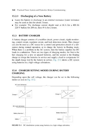
the small charge lost by the battery in service. Fig. 15.1 shows a DC system
using batteries in a high-voltage substations.
15.4 CHARGER SETTING MODES DURING BATTERY
CHARGING
Depending upon the cell voltage, the charger can be set in the following
modes as seen in Fig. 15.2.
FIGURE 15.1 DC distribution system using batteries in a high-voltage substation.