
Page 166 - Practical Power System and Protective Relays Commissioning
P. 166
166 Practical Power System and Protective Relays Commissioning
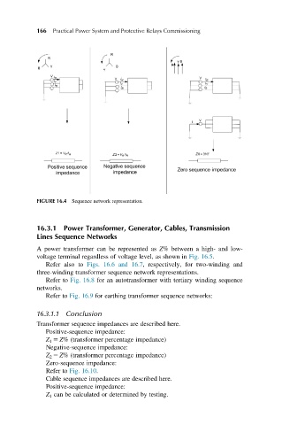
FIGURE 16.4 Sequence network representation.
16.3.1 Power Transformer, Generator, Cables, Transmission
Lines Sequence Networks
A power transformer can be represented as Z% between a high- and low-
voltage terminal regardless of voltage level, as shown in Fig. 16.5.
Refer also to Figs. 16.6 and 16.7, respectively, for two-winding and
three-winding transformer sequence network representations.
Refer to Fig. 16.8 for an autotransformer with tertiary winding sequence
networks.
Refer to Fig. 16.9 for earthing transformer sequence networks:
16.3.1.1 Conclusion
Transformer sequence impedances are described here.
Positive-sequence impedance:
Z 1 5 Z% (transformer percentage impedance)
Negative-sequence impedance:
Z 2 5 Z% (transformer percentage impedance)
Zero-sequence impedance:
Refer to Fig. 16.10.
Cable sequence impedances are described here.
Positive-sequence impedance:
Z 1 can be calculated or determined by testing.