
Page 181 - Practical Power System and Protective Relays Commissioning
P. 181
182 Practical Power System and Protective Relays Commissioning
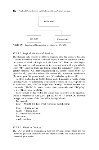
FIGURE 17.1 Functions within substations as reflected in IEC 61850.
17.2.1.1 Logical Nodes and Services
The standard data consists of different logical nodes; the access to this data
is called the service method. There are logical nodes for automatic control,
the names of which all begin with the letter “A.” There are also logical
nodes for metering and measurement, the names of which all begin with the
letter “M.” Likewise there are logical nodes for supervisory control (C),
generic functions (G), interfacing/archiving (I), system logical nodes (L),
protection (P), protection related (R), sensors (S), instrument transformers
(T), switchgear (X), power transformers (Y), and other equipment (Z).
A CB is modeled as an XCBR logical node. It contains a variety of data
including “Loc” for determining if operation is remote or local, “OpCnt” for
an operations count, “Pos” for the position, “BlkOpn” for block breaker open
commands, “BlkCls” for block breaker close commands, and “CBOpCap”
for the CB operating capability.
Each element of data within the logical node conforms to the specifica-
tion of a common data class (CDC) per IEC 61850-7-3. Each CDC describes
the type and structure of the data within the logical node.
For example:
Relay1 XCBR1 ST Loc stVal represents the following:
Relay1 5 logical device
XCBR1 5 logical node
ST 5 functional constraints
Loc 5 data
stVal 5 attribute
17.2.1.2 Physical Devices
The LAN is used to communicate between physical nodes. There are two
interfaces: physical interfaces between physical nodes, and logical interfaces
between logical nodes.