
Page 22 - Practical Power System and Protective Relays Commissioning
P. 22
Substations Chapter | 2 17
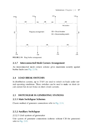
FIGURE 2.10 Ring busbar arrangement.
2.3.7 Interconnected Mesh Corners Arrangement
An interconnected mesh corners scheme gives maximum security against
busbar faults (see Fig. 2.13).
2.4 LOAD BREAK SWITCHES
In distribution systems, up to 33 kV are used to switch on loads under nor-
mal operating conditions. These switches can be used to make on short cir-
cuit current but do not brake on short circuit currents.
2.5 SWITCHGEAR IN GENERATING STATIONS
2.5.1 Main Switchgear Schemes
Classic method of generator connections refer to Fig. 2.14.
2.5.2 Auxiliary Switchgear
2.5.2.1 Unit system of generator
Unit system of generator connections (scheme without C.B for generator)
refer to Fig. 2.15.