Basic HTML Version
Table of Contents
View Full Version
Page 20 - Practical Power System and Protective Relays Commissioning
P. 20
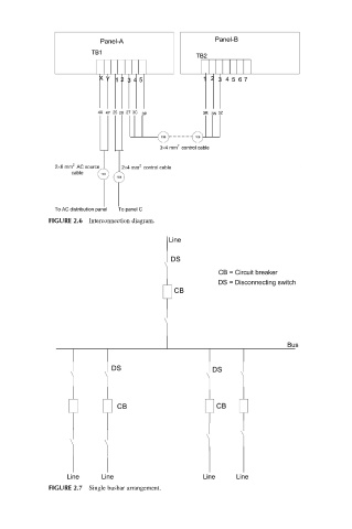
FIGURE 2.6 Interconnection diagram.


             FIGURE 2.7 Single busbar arrangement.
15
16
17
18
19
20
21
22
23
24
25