
Page 16 - Practical Power System and Protective Relays Commissioning
P. 16
Substations Chapter | 2 11
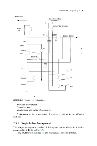
FIGURE 2.2 Protection single line diagram.
Provision of extension.
Protective zones.
Maintenance and safety of personnel.
A discussion of the arrangement of busbars is outlined in the following
sections.
2.3.1 Single Busbar Arrangement
This simple arrangement consists of three-phase busbar with various feeders
connected to it. Refer to Fig. 2.7.
Total shutdown is required for any maintenance to be undertaken.