
Page 15 - Practical Power System and Protective Relays Commissioning
P. 15
10 Practical Power System and Protective Relays Commissioning
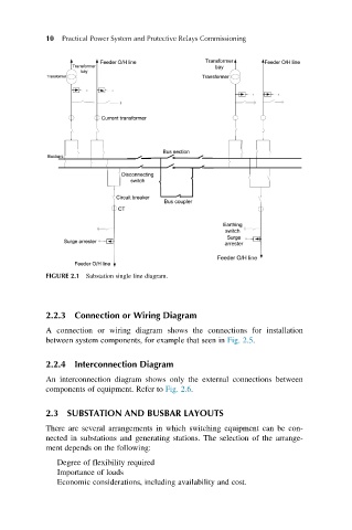
FIGURE 2.1 Substation single line diagram.
2.2.3 Connection or Wiring Diagram
A connection or wiring diagram shows the connections for installation
between system components, for example that seen in Fig. 2.5.
2.2.4 Interconnection Diagram
An interconnection diagram shows only the external connections between
components of equipment. Refer to Fig. 2.6.
2.3 SUBSTATION AND BUSBAR LAYOUTS
There are several arrangements in which switching equipment can be con-
nected in substations and generating stations. The selection of the arrange-
ment depends on the following:
Degree of flexibility required
Importance of loads
Economic considerations, including availability and cost.