
Page 18 - Practical Power System and Protective Relays Commissioning
P. 18
Substations Chapter | 2 13
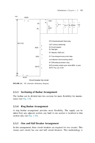
FIGURE 2.4 DC schematic elementary diagram.
2.3.3 Sectioning of Busbar Arrangement
The busbar can be divided into two sections for more flexibility for mainte-
nance (see Fig. 2.9).
2.3.4 Ring Busbar Arrangement
A ring busbar arrangement provides more flexibility. The supply can be
taken from any adjacent section; any fault in one section is localized to that
section only (see Fig. 2.10).
2.3.5 One and Half Breaker Arrangement
In this arrangement, three circuit breakers are required for two circuits. This
means each circuit has one and half circuit breakers. This methodology is