
Page 49 - Practical Power System and Protective Relays Commissioning
P. 49
Generators and Motors: Theory and Testing Chapter | 4 45
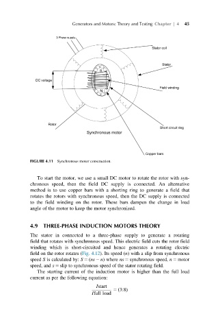
FIGURE 4.11 Synchronous motor construction.
To start the motor, we use a small DC motor to rotate the rotor with syn-
chronous speed, then the field DC supply is connected. An alternative
method is to use copper bars with a shorting ring to generate a field that
rotates the rotors with synchronous speed, then the DC supply is connected
to the field winding on the rotor. These bars dampen the change in load
angle of the motor to keep the motor synchronized.
4.9 THREE-PHASE INDUCTION MOTORS THEORY
The stator in connected to a three-phase supply to generate a rotating
field that rotates with synchronous speed. This electric field cuts the rotor field
winding which is short-circuited and hence generates a rotating electric
field on the rotor rotates (Fig. 4.12). Its speed (n) with a slip from synchronous
speed S is calculated by: S5 (ns2 n)where ns5 synchronous speed, n5 motor
speed, and s5 slip to synchronous speed of the stator rotating field.
The starting current of the induction motor is higher than the full load
current as per the following equation:
Istart
5 3:8Þ
ð
Ifull load