
Page 56 - Practical Power System and Protective Relays Commissioning
P. 56
Power Transformers Theory Testing and Commissioning Chapter | 5 53
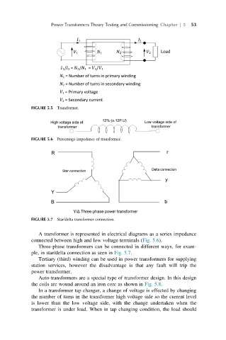
FIGURE 5.5 Transformer.
FIGURE 5.6 Percentage impedance of transformer.
FIGURE 5.7 Star/delta transformer connection.
A transformer is represented in electrical diagrams as a series impedance
connected between high and low voltage terminals (Fig. 5.6).
Three-phase transformers can be connected in different ways, for exam-
ple, in star/delta connection as seen in Fig. 5.7.
Tertiary (third) winding can be used in power transformers for supplying
station services, however the disadvantage is that any fault will trip the
power transformer.
Auto-transformers are a special type of transformer design. In this design
the coils are wound around an iron core as shown in Fig. 5.8.
In a transformer tap changer, a change of voltage is effected by changing
the number of turns in the transformer high voltage side so the current level
is lower than the low voltage side, with the change undertaken when the
transformer is under load. When in tap changing condition, the load should