
Page 57 - Practical Power System and Protective Relays Commissioning
P. 57
54 Practical Power System and Protective Relays Commissioning
FIGURE 5.8 Auto-transformer.
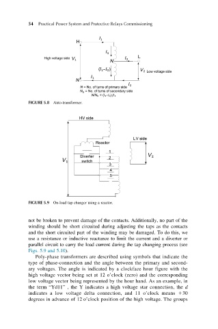
FIGURE 5.9 On-load tap changer using a reactor.
not be broken to prevent damage of the contacts. Additionally, no part of the
winding should be short circuited during adjusting the taps as the contacts
and the short circuited part of the winding may be damaged. To do this, we
use a resistance or inductive reactance to limit the current and a diverter or
parallel circuit to carry the load current during the tap changing process (see
Figs. 5.9 and 5.10).
Poly-phase transformers are described using symbols that indicate the
type of phase-connection and the angle between the primary and second-
ary voltages. The angle is indicated by a clockface hour figure with the
high voltage vector being set at 12 o’clock (zero) and the corresponding
low voltage vector being represented by the hour hand. As an example, in
the term “Yd11” , the Y indicates a high voltage star connection, the d
indicates a low voltage delta connection, and 11 o’clock means 130
degrees in advance of 12 o’clock position of the high voltage. The groups