
Page 125 - Practical Ship Design
P. 125
92 Chapter 4
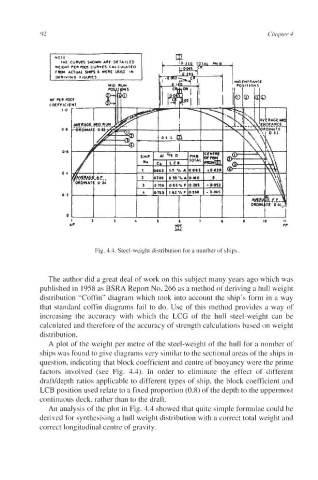
Fig. 4.4. Steel-weight distribution for a number of ships.
The author did a great deal of work on this subject many years ago which was
published in 1958 as BSRA Report No. 266 as a method of deriving a hull weight
distribution “Coffin” diagram which took into account the ship’s form in a way
that standard coffin diagrams fail to do. Use of this method provides a way of
increasing the accuracy with which the LCG of the hull steel-weight can be
calculated and therefore of the accuracy of strength calculations based on weight
distribution.
A plot of the weight per metre of the steel-weight of the hull for a number of
ships was found to give diagrams very similar to the sectional areas of the ships in
question, indicating that block coefficient and centre of buoyancy were the prime
factors involved (see Fig. 4.4). In order to eliminate the effect of different
draftldepth ratios applicable to different types of ship, the block coefficient and
LCB position used relate to a fixed proportion (0.8) of the depth to the uppermost
continuous deck, rather than to the draft.
An analysis of the plot in Fig. 4.4 showed that quite simple formulae could be
derived for synthesising a hull weight distribution with a correct total weight and
correct longitudinal centre of gravity.