
Page 129 - Practical Ship Design
P. 129
96 Chapter 4
urn ENIRAUCC
mnm
I I I 1 I I
06 07 OS 10
MI0 RW fAClOR
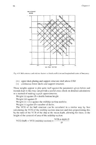
Fig. 4.9. Mid-entrance and mid-run factors vs block coefficient and longitudinal centre of buoyancy.
(iv) upper deck plating and support structure shell above 0.9D
(v) continuous lower decks and support structure.
These weights appear to plot quite well against the parameters given below and
records kept in this way can provide a useful cross check on detailed calculations
or a method of making a quick approximation.
Weight (ii) against B x double bottom height
Weight (iii) against D
Weight (i) + (iv) against the midship section modulus
Weight (v) against B x number of decks.
The VCG of the hull structure can be calculated in a similar way by first
calculating the VCG of the midship section structure and then proportioning this
by the ratio of the VCB of the ship at the mean depth, allowing for sheer, to the
height of the centroid of area of the midship section.
VCB at depth D
VCG (hull) = VCG (midship section) x
D