
Page 127 - Practical Ship Design
P. 127
94 Chapter 4
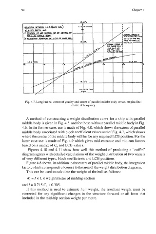
Fig. 4.7. Longitudinal centre of gravity and centre of parallel middle body versus longitudinal
centre of buoyancy.
A method of constructing a weight distribution curve for a ship with parallel
middle body is given in Fig. 4.5, and for those without parallel middle body in Fig.
4.6. In the former case, use is made of Fig. 4.8, which shows the extent of parallel
middle body associated with block coefficient values and of Fig. 4.7, which shows
where the centre of the middle body will be for any required LCB position. For the
latter case use is made of Fig. 4.9 which gives mid-entrance and mid-run factors
based on a matrix of C, and LCB values.
Figures 4.10 and 4.1 1 show how well this method of producing a “coffin”
diagram agrees with detailed calculations of the weight distribution of two vessels
of very different types, block coefficients and LCB positions.
Figure 4.8 shows, in addition to the extent of parallel middle body, the integration
factor, which corresponds of course to the area of the weight distribution diagrams.
This can be used to calculate the weight of the hull as follows:
W, = Z x L x weighdmetre of midship section
and Z= 0.715 C, + 0.305.
If this method is used to estimate hull weight, the resultant weight must be
corrected for any significant changes in the structure forward or aft from that
included in the midship section weight per metre.