
Page 187 - Pressure Vessel Design Manual
P. 187
Design of Vessel Supports 165
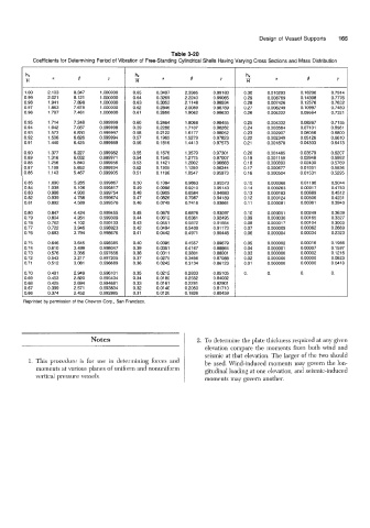
Table 3-20
Coefficients for Determining Period of Vibration of Free-Standing Cylindrical Shells Having Varying Cross Sections and Mass Distribution
~
a Y a B Y a B Y
1 .oo 2.103 8.347 1 .o0oooo 0.65 0.3497 2.3365 0.99183 0.30 0.010293 0.16200 0.7914
0.99 2.021 8.121 1 .o0oooo 0.64 0.3269 2.2240 0.99065 0.29 0.008769 0.14308 0.7776
0.98 1.941 7.898 1 .o00000 0.63 0.3052 2.1148 0.98934 0.28 0.007426 0.12576 0.7632
0.97 1.863 7.678 1 .oooooo 0.62 0.2846 2.0089 0.98789 0.27 0.006249 0.10997 0.7480
0.96 1.787 7.461 1 .oooooo 0.61 0.2650 1.9062 0.98630 0.26 0.005222 0.09564 0.7321
0.95 1.714 7.248 0.999999 0.60 0.2464 1 BO68 0.98455 0.25 0.004332 0.08267 0.71 55
0.94 1.642 7.037 0.999998 0.59 0.2288 1.7107 0.98262 0.24 0.003564 0.07101 0.6981
0.93 1.573 6.830 0.999997 0.58 0.2122 1.6177 0.98052 0.23 0.002907 0.06056 0.6800
0.92 1 SO6 6.626 0.999994 0.57 0.1965 1.5279 0.97823 0.22 0.002349 0.05126 0.661 0
0.91 1.440 6.425 0.999989 0.56 0.1816 1.4413 0.97573 0.21 0,001878 0.04303 0.6413
0.90 1.377 6.227 0.999982 0.55 0.1676 1.3579 0.97301 0.20 0,001485 0.03579 0.6207
0.89 1.316 6.032 0.999971 0.54 0.1545 1.2775 0.97007 0.19 0.001 159 0.02948 0.5992
0.88 1.256 5.840 0.999956 0.53 0.1421 1 .zoo2 0.96688 0.18 0.000893 0.02400 0.5769
0.87 1.199 5.652 0.999934 0.52 0.1305 1.1259 0.96344 0.17 0.000677 0.01931 0.5536
0.86 1.143 5.467 0.999905 0.51 0.1196 1.0547 0.95973 0.16 0.000504 0.01531 0.5295
0.85 1.090 5.285 0.999867 0.50 0.1094 0.9863 0.95573 0.15 0.000368 0.01 196 0.5044
0.84 1.038 5.106 0.99981 7 0.49 0.0998 0.9210 0.95143 0.14 0.000263 0.0091 7 0.4783
0.83 0.988 4.930 0.999754 0.48 0.0909 0.8584 0.94683 0.13 0.000183 0.00689 0.4512
0.82 0.939 4.758 0.999674 0.47 0.0826 0.7987 0.94189 0.12 0.000124 0.00506 0.4231
0.81 0.892 4.589 0.999576 0.46 0.0749 0.7418 0.93661 0.1 1 0.000081 0.00361 0.3940
0.80 0.847 4.424 0.999455 0.45 0.0678 0.6876 0.93097 0.10 0.000051 0.00249 0.3639
0.79 0.804 4.261 0.999309 0.44 0.0612 0.6361 0.92495 0.09 0.000030 0.00165 0.3327
0.78 0.762 4.102 0,999133 0.43 0.0551 0.5872 0.91854 0.08 0.000017 0.00104 0.3003
0.77 0.722 3.946 0.998923 0.42 0.0494 0.5409 0.91 173 0.07 0.000009 0.00062 0.2669
0.76 0.683 3.794 0.998676 0.41 0.0442 0.4971 0.90448 0.06 0.000004 0.00034 0.2323
0.75 0.646 3.645 0.998385 0.40 0.0395 0.4557 0.89679 0.05 0.000002 0.00016 0.1 966
0.74 0.61 0 3.499 0.998047 0.39 0.0351 0.4167 0.88864 0.04 0.000001 0.00007 0.1597
0.73 0.576 3.356 0.997656 0.38 0.031 1 0.3801 0.88001 0.03 0.000000 0.00002 0.1216
0.72 0.543 3.217 0.997205 0.37 0.0275 0.3456 0.87088 0.02 0.000000 0.00000 0.0823
0.71 0.512 3.081 0.996689 0.36 0.0242 0.3134 0.86123 0.01 0.000000 0.00000 0.0418
0.70 0.481 2.949 0.9961 01 0.35 0.0212 0.2833 0.85105 0. 0. 0. 0.
0.69 0.453 2.820 0.995434 0.34 0.0185 0.2552 0.84032
0.68 0.425 2.694 0.994681 0.33 0.0161 0.2291 0.82901
0.67 0.399 2.571 0.993834 0.32 0.0140 0.2050 0.81710
0.66 0.374 2.452 0.992885 0.31 0.0120 0.1826 0.80459
Reprinted by permission of the Chevron Corp., San Francisco.
Notes 2. To determine the plate thickness required at any given
elevation compare the moments from both wind and
seismic at that elevation. The larger of the two should
1. This procedure is for use in determining forces and be used. Wind-induced moments may govern the lon-
moments at various planes of uniform and nonuniform gitudinal loading at one elevation, and seismic-induced
vertical pressure vessels. moments may govern another.