
Page 189 - Pressure Vessel Design Manual
P. 189
Design of Vessel Supports 167
r
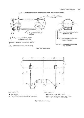
S,-3 = longitudinal bending at saddles (tension at top, compression at bottom)
S14 = circumferential stress
in stiffener
S,* = circumferential compression
S,, = longitudinal bending at at bottom of shell
shell
bottom
of
at
midspan
SS-, = tangential shear-results = circumferential compression
in diagonal lines in shell
in plane of saddle
Sa = tangential shear in head (A 5 RE)
S9-ro = circumferential bending at
Slr = additional tension in head (A I R12) horn of saddle
Figure 3-43. Stress diagram.
Ir
Id
L12 1 L12 c
'\
I ' I I I'
is negative for M2 is positive for
Hemi-heads. 0 Flat heads where A/R < 0.707.
0 If any of the below conditions are exceeded. 100%-6% F&D heads where A/R < 0.44.
0 2:l S.E. heads where NR < 0.363.
Figure 3-44. Moment diagram.