
Page 194 - Pressure Vessel Design Manual
P. 194
172 Pressure Vessel Design Manual
Table 3-23 S4 = longitudinal bending at midspan, tension at
Coefficient, K, bottom, compression at top
S5 =tangential shear-shell stiffened in plane of
Height (ft) KZ
saddle
0-1 5 0.85 S6 =tangential shear-shell not stiffened, A P W2
20 0.9 S7 = tangential shear-shell not stiffened except by
25 0.94
30 0.98 heads, A 5 W2
40 1.04 Ss = tangential shear in head-shell not stiffened,
50 1.09 A5W2
60 1.13 Sg = circumferential bending at horn of saddle-
shell not stiffened, L 2 8R
0 Transverse forces, Ft, per saddle. S 10 = circumferential bending at horn of saddle-
shell not stiffened, L < 8R
Seismic:
SI1 =additional tension stress in head, shell not stif-
Ft = ( ChW0)0.5 fened, A 5 W2
Wind: SI2 = circumferential compressive stress-stiffened
or not stiffened, saddles attached or not
Ft = (Af cf Gdq8.5 SI3 = circumferential stress in shell with stiffener in
Af= D,(L + 2H) plane of saddle
SI4 = circumferential stress in ring stiffener
0 Total saddle reaction forces, Q.
Longitudinal Bending
Q =greater of Q1 or Q2
Longitudinal, Ql 0 SI, longitudinal bending at saddles-without stiffeners,
tension.
8AH + 6A2 - 3R2 + 3H2 1
3L+4H
Transverse, Qz M1
SI = (+>-
Klrzts
0 Sg, longitudinal bending at saddles-without stiffeners,
compression.
MI
Shell Stresses s2 = (-)- K7r2t,
There are 14 main stresses to be considered in the design 0 S3, longitudinal bending at saddles-with stiffeners.
of a horizontal vessel on saddle supports:
SI= longitudinal bending at saddles without stif-
feners, tension
S2 = longitudinal bending at saddles without stif- e Sq, longitudinal bending at midspan.
feners, compression
S3 = longitudinal bending at saddles with stiffeners 3L2 + 6R2 - 6H2 - 12AL - 16AH
Mz = 3Q[ 1
3L + 4H
s4 = (&)- M2
m2ts
Tangential Shear
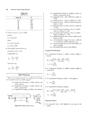
0 S5, tangential shear-shell stiflened in the plane of the
Figure 3-46. Saddle reaction forces. saddle.