
Page 193 - Pressure Vessel Design Manual
P. 193
Design of Vessel Supports 171
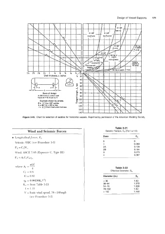
Figure 3-45. Chart for selection of saddles for horizontal vessels. Reprinted by permission of the American Welding Society.
Table 3-21
Wind and Seismic Forces Seismic Factors, C, (For I = 1 .O)
e Longitudinnl J;)rcPE, F,,. Zone cs
0 0
Seismic: UBC (see Procedure 3-3)
1 0.069
2A 0.138
FL, = C;l,\f’,,
28 0.184
M’ind: ASCE 7-9.5 (Exposure C, Type 111) 3 0.275
4 0.367
Fl, = A1 GJ~,
Table 3-22
Effective Diameter, De
Cf = 0.8
G = 0.85 Diameter (in.) D,
q, = 0.00256KzV21 e 36 1.5D
K, = from Table 3-23 36-54 1.370
54-78 1.28D
I = 1.15 78-1 02 1.2D
V = basic: wind speed, YO- 100 rnph > 102 1.18D
(see Procedure 3-2)