
Page 188 - Pressure Vessel Design Manual
P. 188
166 Pressure Vessel Design Manual
PROCEDURE 3-10
DESIGN OF HORIZONTALVESSEL ON SADDLES [I, 3, 5, 14, 151
S = allowable stress, tension, psi
~
Notation S, =allowable stress, compression, psi
S1-14 = shell, head, and ring stresses, psi
A, = cross-sectional area of composite ring stiffen- K1-9 = coefficients
er, in. 2 FL = longitudinal force due to wind, seismic, expan-
Af = projected area of vessel, ft2 sion, contraction, etc., lb
E =joint efficiency FT =transverse force, wind or seismic, lb
El = modulus of elasticity, psi ax = longitudinal stress, internal pressure, psi
Ch = seismic factor (see Procedure 3-3) c+ = circumferential stress, internal pressure, psi
Cf = shapefactor = 0.8 a,, = longitudinal stress, external pressure, psi
q, =wind pressure, psf as = circumferential stress in stiffening ring, psi
De = effective vessel diameter, ft ah = latitudinal stress in head due to internal pres-
I~ = moment of inertia of ring stiffener, in.4 sure, psi
t, = thickness of wear plate, in. F, = minimum yield stress, shell, psi
t, =thickness of shell, in. P = internal pressure, psi
th =thickness of head, in. P,, = external pressure, psi
Q =total load per saddle (including piping loads, G = gust factor, wind
wind or seismic reactions, platforms, operating K, =velocity pressure coefficient
liquid, etc.) lb I =importance factor, 1.el.25 for vessels
W, = operating weight of vessel, lb V =basic wind speed, mph
MI = longitudinal bending moment at saddles, in.-lb K, = pier spring rate, 46 k.
M2 = longitudinal bending moment at midspan, ~.l. = friction coefficient
in. -1b y =pier deflection, in.
R, E mean radius, in.
R
,- = radius, ft
l' = 1.56 fi
Stiffening
ring
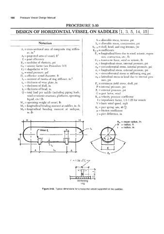
Figure 3-42. Typical dimensions for a horizontal vessel supported on two saddles.