Page 210 - Pressure Vessel Design Manual
P. 210

188    Pressure Vessel Design Manual

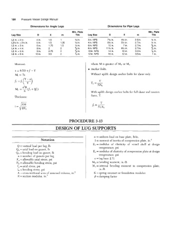
                       Dimensions for Angle Legs                             Dimensions for Pipe Legs
                                                    Min. Plate                                           Min. Plate
         Leg Size          D        X       rn        Thk      Leg Size       D         E        rn        Thk
         L2 in. x 2 in.    4 in.   1.5      1         % in.    3in. NPS     7% in.    4%  in.   2.5 in.    % in.
         L2% in. x 2% in.   5 in.   1.5     1.25      % in.    4in. NPS     8% in.    5% in.    2.7 in.    % in.
         L3 in. x 3 in.    6 in.   1.75     1.5       M in.    6in. NPS      10 in.    7 in.    2.7 in.    % in.
         L4 in. x 4 in.    8 in.   2       2          % in.    8in. NPS     11% in.   8% in.    2.7 in.    ?,  in.
         L5 in. x 5 in.    9 in.   2.75    2          % in.    loin. NPS     14 in.    10 in.   3.2 in.    '/8 in.
         L6 in. x 6 in.   10 in.   3.5     2          ?,  in.   12in. NPS    16 in.    12 in.   3.5 in.     1 in.


           Moment                                                where M is greater of MT  or M,.
                                                               e Anchor bolts.
            x = 0.5D +f - Y
            Mt  = TX                                             Without uplift: design anchor bolts for shear only.
                  Y-a
           f1 =h(y)                                              T --
                                                                       V
                                                                   -  NA,,
                 a2 B
            Mc =  6    + 2f4
                                                                 With uplift: design anchor bolts for full shear and tension
           Thickness:                                            force, T.
                                                                       T
           t   =  g                                               h=-


                                                  PROCEDURE 3-13

                                        DESIGN OF LUG SUPPORTS


                                                                   w = uniform load on base plate, Ib/in.
                              Notation                             I = moment of inertia of compression plate, in.4
                                                                  E,=modulus   of  elasticity  of  vessel  shell  at  design
             Q =vertical  load per lug, Ib
             Qa =axial  load on gusset, Ib                             temperature, psi
            Qt, =bending  load on gusset, lb                      E, = modulus of elasticity of compression plate at design
              n = number  of gussets per lug                          temperature, psi
             Fa = allowable axial stress, psi                      e =log  base 2.71
             Fb = allowable bending stress, psi                   Mb =bending  moment, in.-lb
             fa =axial  stress, psi                               M, =internal  bending  moment  in  compression  plate,
             fb =bending  stress, psi                                  in.-lb
             A =cross-sectional  area of assumed column, in?       K = spring constant or foundation  modulus
             Z = section modulus, in.  3                             = damping factor
   205   206   207   208   209   210   211   212   213   214   215