Page 209 - Pressure Vessel Design Manual
P. 209

Design of Vessel Supports   187


                                                             1                              n


                                     B


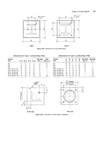
                                             Figure 3-62.  Dimensions for base plates-beams.


                 Dimensions for Type 1+2)  Bolt Base Plate            Dimensions for Type 2-4)   Bolt Base Plate
          Column                            Min Plate   Max     Column        D,   B,   G,  E,   W,   Min Plate  Max Bolt
          Size          D, in.  B, in.  E, in.  W, in.  Thk, in.  Bolt 4, in.   Size   in.  in.  In.  in.   in.   Thk, in.   4, in.
                               ~~   ~~        ~      ~
          w4             8    8    4    %      23      t        w4            10  10   7   7   %    %         1
                                                        4
          W6             8    8    4    %      %       3        W6            12  12   9   9   5/16   3/,     1
                                                        4
          wa             10   10    6   ’/4    %       3        wa            15  15  11  11  %     3/,       1
          W10-33thru45   12   12    6   5/16   74       1       W10-33  thru 45   17  15  13  11  %   ?3     1%
          W10-49  thru 112   13   13   6   5/16   /4    1       W10-49  thru 112  17  17  13  13  %   23     1%
          W12-40thru50   14   10   6    5/16   23       1       W12-40  thru 50   19  15  15  11  %   1      1%
          W12-53thru58   14   12   6    5/re   D        1       W12-53  thru 58   19  17  15  13  %   1      1%
          W12-65thru  152   15   15   8   5/r6   D     1%       W12-65  thW  152  19  19  15  15  %   1      1%


                                                                        +     “D” Square
                                                                               “E” Square   1


                                                                                   I
                              i   m                                                I
                                T
                                Angle Legs                                      Pipe Legs
                                           Figure 3-63.  Dimensions for base plates-angle/pipe.
   204   205   206   207   208   209   210   211   212   213   214