Page 205 - Pressure Vessel Design Manual
P. 205

Design of  Vessel Supports   183

                                Ribs                           a  Bending stress, fi, = 0.66 Fy.


                                                                      MC1
               Outside Ribs                                      fb =-  I

                                                               a  Combined stress.

                                                                      fh
                                                                  fa
                                                                 -+-<l
                                                                  Fa  Fb

                                                               Inside Ribs

                                                                                 I          / Inside rib


                         A,  = a area of rib and web, in.*
                         Ap =   pressure area, = 0.5Fe
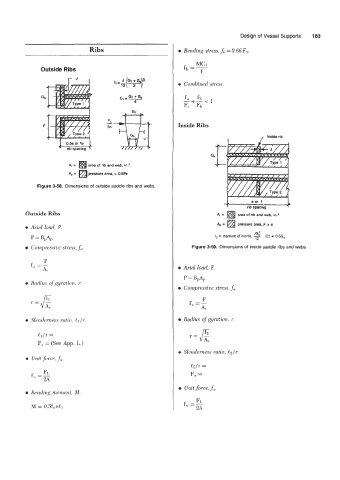
              Figure 3-58.  Dimensions of  outside saddle ribs and webs.


                                                                                         eor  1       1 1
                                                                                1       rib spacing
          Outside Ribs                                                       4 =    area of  rib and web, in.*
                                                                               =
                                                                             4 a pressure area, F x e
          0  Az-ial load, P.
                                                                                          JG;
            P = B,A,                                                         l2  = moment of  inertia, - C2 = 0.5Gb
                                                                                           12
          0  Compressiue stress, fa.                                Figure 3-59,  Dimensions of  inside saddle ribs and webs.

                 P
            fa =A,                                              0  Axial load, P.
                                                                  P = BDAP
          a  Radius of  gyration, r.
                                                                0  Compressive stress, fa.
                                                                        P
            r=g                                                     f  --
                                                                    a-  A,
                                                                    r=e
          0  Slenderness ratio, e1 /r.                          0  Radius of gyration, r.

              ll/r =
              F;, = (See App. L.)
                                                                a  Slenderness ratio, &/r.
          a  Unit $me, f;,.
                                                                    &/r  =
                Fr.                                                 Fa =
            f,, =
                                                                0  Unit force. J;,.
          a  Bending moment, M.

                                                                      F1,
            M = 0.5f,,el1                                         f  --
                                                                   " - 2A
   200   201   202   203   204   205   206   207   208   209   210