
Page 202 - Pressure Vessel Design Manual
P. 202
180 Pressure Vessel Design Manual
A Y AY AV b Note: Circumferential bending at
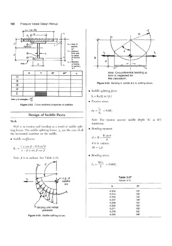
horn is neglected for
0 this calculation.
Q
Figure 3-54. Bending in saddle due to splitting forces.
c I I I 1 0 Saddle splitting force.
Nors: lo for rectangles I - fh=Kl(Q Or QT)
bh3
12 0 Tension stress.
Figure 3-52. Cross-sectional properties of saddles.
fh
CJT = - < 0.6FY
Design of Saddle Parts As
Note: For tension assume saddle depth "h" as FV3
Web
maximum.
Web is in tension and bending as a result of saddle split-
ting forces. The saddle splitting forces, fh, are the sum of all 0 Bending moment.
the horizontal reactions on the saddle. R sin8
d=B--
0 Saddle coeflicient. Q
Q is in radians.
1 + cos /3 - 0.5 sin2B
K1 = M = fhd
n - /3+ sin /3 cos /3
0 Bending stress.
Note: /3 is in radians. See Table 3-18.
MC1
<
fb = - 0.66FY
I
Table 3-27
Values of kl
kl 213
0.204 120"
0.214 126"
0.226 132"
0.237 138"
0.248 144"
0.260 150"
Varying unit radial 0.271 156"
pressure 0.278 162"
0.294 168"
Figure 3-53. Saddle splitting forces.