
Page 201 - Pressure Vessel Design Manual
P. 201
Design of Vessel Supports 179
n := number of ribs, including outer ribs, in one saddle Maximum Loads
P I equivalent column load, lb
d = distance from base to centroid of saddle arc, in. Vertical.
W,, operating weight of vessel + contenty, lb greater of Q1, QZ, or QT
=
WT = vessel weight full of water, lb
mT =tension stress, psi QI = Qo + Qii
w = uniform load, lb Q2 = Qo + QL
0 Longitudinal.
~~~ ~ FI, = greater of FLi through FT.(,
Forces and Loads
(see procedure 3-10 for definitions)
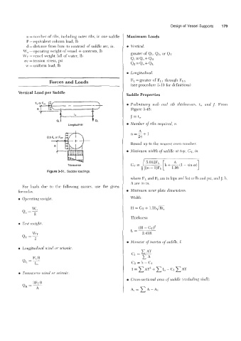
Vertical Load per Saddle Saddle Properties
Feor Fm E{ - 0 Prelimhay web and rib tlzicknesses, t,, ancl 1. From
B i Figure 3-45:
7
L,
J = tw
QL Number of ribs required, n.
Longitudinal
A
n=-+1
24
Round up to the nearest even nuinher.
0 Minimum width of saddle ut top, G7; in
Transverse
Figure 3-51. Saddte loadings.
where FIJ and F1, are in kips and ksi or Ib and psi, and J, 11,
A are in in.
For loads due to the following causes, use the given
formulas. 0 Minimum wear plute dinrensiom.
0 Opcmting iveiglif Width:
€I = GT + 1.56&
Thickness:
Test weight.
(H - GT)~
t, =
2.43R
Moment of inertia of sculclle, I.
Longitudinal wind or seismic.
c AY
c1=-
C*
c2 = 11 - c1
I = CAY^ +XI<, CAY
C,
-
0 Transwrw wind or seisvnic.
e Cross-sectional urea if sacldle (editling shell).
B
~FT
QH =A
A, = A- Ai