
Page 203 - Pressure Vessel Design Manual
P. 203
Design of Vessel Supports 181
I fb 1
h I 4
.- ,I :I::#
ft tlttftti1
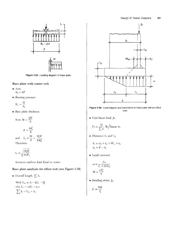
Figure 3-55. Loading diagram of base plate. /
Base plate with center web
e Area.
Ab = AF 1
c2 (1
e Bearing pressure. 1
v 1 F 1
B -- 1
- AI,
Figure 3-56. Load diagram and dimensions for base plate with an offset
0 Bme plate thickness. web.
QF e Unit linear load, ji.
NOW M =-
8
A$ fu = & lb/linear in.
Z=-
6
M 3QF e Distances and e,.
and f,, = - = __
Z 4Atf
Therefore
e Loads moment.
Assumes uniform load fured in center.
Base plate analysis for offset web (see Figure 3-56)
Ozjernll length, C L.
a Bending stress, fb.
Web L, = A - 2dl- 2J
ribs L, = n(G - t,) fh =F
6M
CL=L,.,+L,