
Page 204 - Pressure Vessel Design Manual
P. 204
182 Pressure Vessel Design Manual
Anchor Bolts
Anchor bolts are governed by one of the three following
load cases:
1. Longitudinal load: If Qo > QL, then no uplift occurs,
and the minimum number and size of anchor bolts
should be used.
If Qo < QL, then uplift does occur:
QL - Qo = load per bolt
.N
2. Shear: Assume the fNed saddle takes the entire shear
load.
FL
- = shear per bolt
N
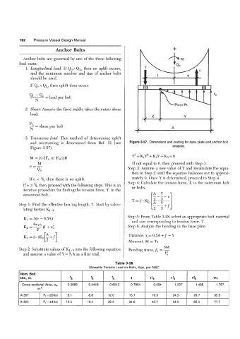
3. Transverse load: This method of determining uplift
and overturning is determined from Ref. 21 (see Figure 3-57. Dimensions and loading for base plate and anchor bolt
Figure 3-57). analysis.
M = (0.5Fe or Fw)B Y3 + K,Y2 + KzY + K3 = 0
M If not equal to 0, then proceed with Step 3.
e=- Step 3: Assume a new value of Y and recalculate the equa-
Qo
tion in Step 2 until the equation balances out to approxi-
If e < "/6, then there is no uplift. mately 0. Once Y is determined, proceed to Step 4.
Step 4: Calculate the tension force, T, in the outermost bolt
If e 3 %, then proceed with the following steps. This is an or bolts.
iterative procedure for finding the tension force, T, in the
outermost bolt. I-A Y 1
Step 1: Find the effective bearing length, Y. Start by calcu-
lating factors K1a,
Step 5: From Table 3-28, select an appropriate bolt material
Ki = 3(e - 0.5A) and size corresponding to tension-force, T.
6nlat
(f + e)
Kz = - Step 6: Analyze the bending in the base plate.
F
Distance, x = 0.5A +f - Y
Moment, M = Tx
6M
Step 2: Substitute values of K1-3 into the following equation Bending stress,fb = -
and assume a value of Y = %A as a first trial. t"b
Allowable Tension Load on Bolts, Kips, per AlSC
~ Nom. Bolt
Dia., in. % t 2l 1 1% 1% 1% 1 'h
Cross-sectional Area, ab, 0.3068 0.441 8 0.6013 0.7854 0.994 1.227 1.485 1.767
in.'
A-307 Ft=20ksi 6.1 8.8 12.0 15.7 19.9 24.5 29.7 35.3
A-325 Ft=44ksi 13.5 19.4 26.5 34.6 43.7 54.0 65.3 77.7