Page 208 - Pressure Vessel Design Manual
P. 208

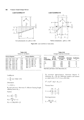
186    Pressure Vessel Design Manual
                   Load Condition #1                                 Load Condition #2


                                                                                                   -Z
                                                                                                   *i
                                                 t                                                 t
                                                                                               '1


                       Full compression, no uplift, e 5 D/6             Partial compression, uplift, e > D/6

                                             Figure 3-61.  Load conditions on base plates.


                              Table 3-29                                           Table 3-30
                          Values of n' for Beams                             Average Properties of Concrete

         Column Section        n'    Column Section      n'                Ult fg   Allowable
                                                               Water       28-Day   Compression,  Allowable  Coefficient,
         W14x730-Wl4x  145    5.77   w10x45-w10x33      3.42   Contenmag  Str (psi)   F,  (psi)   8, (Psi)   n
         w14 x 132 - w14 x 90   5.64   W8 x 67-  W8 x 31   3.14
         W14 x 82 - W14 x 61   4.43   W8 x 28-  W8 x 24   2.77   7.5       2000        800       500        15
                                                  15
         W14x53-  W14x43      3.68    W6~25-W6~         2.38   6.75        2500       1000       625        12
         W12 x 336 - W12 x 65   4.77   W6 x 16 - W6 x 9   1.77   6         3000       1200       750        10
         W12 x 58-  W12 x 53   4.27   W5 x 19- W5 x 16   1.91   5          3750       1400       938        8
         W12 x 50 - W12 x 40   3.61   W4x 13            1.53
         wlox112-wlox49       3.92                             Reprinted by permission of John Wiley & Sons, Inc.
                                                       -

                                                                 By  successive  approximations,  determine  distance  Y.
           Coefficient:
                                                                 Substitute  KI3  into the  following equation  and  assume
               E                                                 an initial value  of^ =%  A as a first trial.
           n = -2 (see Table 3-30)
               E,
                                                                 Y3 + K1Y2 + K2Y + K3 = 0
           Dimension:
           f  = 0.5d+z                                           Tension force:
           By trial  and error, determine Y,  effective bearing length,
           utilizing factors K1-3.                                                e

           Factors:                                              T = (-)P
                                                                         [H-i- ---+f
            K1 =,(e+:)
                                                                 Bearing pressure:

                                                                     2(P + T)
                                                                 f,  = ___   < f:.
                                                                       YB
   203   204   205   206   207   208   209   210   211   212   213