
Page 23 - Pressure Vessel Design Manual
P. 23
10 Pressure Vessel Design Manual
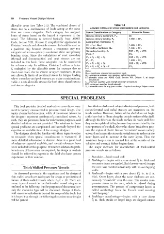
allowable stress (see Table 1-1). The combined classes of Table 1-1
stress due to a combination of loads acting at the same Allowable Stresses for Stress Classifications and Categories
time are stress categories. Each category has assigned Stress Classification or Cateaorv Allowable Stress
limits of stress based on the hazard it represents to the General primary membrane, P, SE
vessel. The following is derived basically from ASME General primary bending, Pb 1.5SE < .9Fy
Code, Section VIII, Division 2, simplified for application to Local primary membrane, PL
Division 1 vessels and allowable stresses. It should be used as (PL=P, +QmJ 1.5SE 4 .9Fy
a guideline only because Division 1 recognizes only two Secondary membrane, Q, 1.5SE < .9Fy
categories of stress-primary membrane stress and primary Secondary bending, Qb 3SE < 2Fy UTS
bending stress. Since the calculations of most secondary Peak, F 2Sa
(thermal and discontinuities) and peak stresses are not pm f Pb + em + Qb 3SE < 2Fy < UTS
included in this book, these categories can be considered pL+ Pb 1.5SE < .9Fy
3SE < 2Fy < UTS
pm + Pb +Q& + Qb
for reference only. In addition, Division 2 utilizes a factor Pm + Pb + Q& + Qb + F 2Sa
K multiplied by the allowable stress for increase due to
Notes:
short-term loads due to seismic or upset conditions. It also Q,, = membrane stresses from sustained loads
sets allowable limits of combined stress for fatigue loading W, =membrane stresses from relenting, self-limiting loads
where secondary and peak stresses are major considerations. S=allowable stress per ASME Code, Section VIII, Division 1, at design
temperature
Table 1-1 sets allowable stresses for both stress classifications F,= minimum specified yield strength at design temperature
and stress categories. UTS = minimum specified tensile strength
S,=allowable stress for any given number of cycles from design fatigue curves.
SPECIAL PROBLEMS
This book provides detailed methods to cover those areas In a thick-walled vessel subjected to internal pressure, both
most frequently encountered in pressure vessel design. The circumferential and radlal stresses are maximum on the
topics chosen for this section, while of the utmost interest to inside surface. However, failure of the shell does not begin
the designer, represent problems of a specialized nature. As at the bore but in fibers along the outside surface of the shell.
such, they are presented here for information purposes, and Although the fibers on the inside surface do reach yield first
detailed solutions are not provided. The solutions to these they are incapable of failing because they are restricted by the
special problems are complicated and normally beyond the outer portions of the shell. Above the elastic-breakdown pres-
expertise or available time of the average designer. sure the region of plastic flow or “overstrain” moves radially
The designer should be familiar with these topics in order outward and causes the circumferential stress to reduce at the
to recognize when special consideration is warranted. If inner layers and to increase at the outer layers. Thus the
more detailed information is desired, there is a great deal maximum hoop stress is reached first at the outside of the
of reference material available, and special references have cylinder and eventual failure begins there.
been included for this purpose. Whenever solutions to prob- The major methods for manufacture of thick-walled
lems in any of these areas are required, the design or analysis pressure vessels are as follows:
should be referred to experts in the field who have proven
experience in their solution. 1. Monobloc-Solid vessel wall.
2. Multilayer-Begins with a core about ‘/z in. thick and
successive layers are applied. Each layer is vented (except
~ ~ ~ ~
Thick-Walled Pressure Vessels the core) and welded individually with no overlapping
welds.
As discussed previously, the equations used for design of 3. Multiwall-Begins with a core about 1% in. to 2 in.
thin-walled vessels are inadequate for design or prediction of thick. Outer layers about the same thickness are suc-
failure of thick-walled vessels where R,,/t < 10. There are cessively “shrunk fit” over the core. This creates com-
many types of vessels in the thick-walled vessel category as pressive stress in the core, which is relaxed during
outlined in the following, but for purposes of discussion here pressurization. The process of compressing layers is
only the monobloc type will be discussed. Design of thick- called autofrettage from the French word meaning
wall vessels or cylinders is beyond the scope of this book, but “self-hooping.”
it is hoped that through the following discussion some insight 4. Multilayer autofirettage-Begins with a core about
will be gained. ‘/z in. thick. Bands or forged rings are slipped outside