
Page 28 - Pressure Vessel Design Manual
P. 28
4
General Design
PROCEDURE 2-1
GENERALVESSEL FORMULAS 11, 21
Notation
P = internal pressure, psi Ellipsoidal or
D,, D, = insidehtside diameter, in. torispherical
S = allowable or calculated stress, psi head -
E =joint efficiency
L =crown radius, in.
K,, R, = insidehutside radius, in.
K, M = coefficients (See Note 3)
crx = longitudinal stress, psi
crTd = circumferential stress, psi
R,,, = mean ra&us of shell, in.
t =thickness or thickness required of shell, head, t-4
or cone, in.
r =knuckle radius, in.
Notes
1. Formulas are valid for:
a. Pressures < 3,000 psi.
b. Cylindrical shells where t 5 0.5 R, or P 5 0.385 SE.
,JK
For thicker shells see Referencr 1, Para. 1-2.
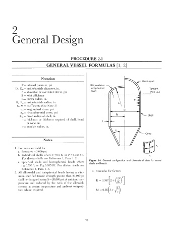
c. Spherical shells and hemispherical heads where Figure 2-1. General configuration and dimensional data for vessel
shells and heads.
t 5 0.356 R, or P 5 0.665 SE. For thicker shells see
Reference 1, Para. 1-3.
2, All ellipsoidal and torispherical heads having a mini- 3. Formulas for factors:
mum specified tensile strength greater than 80,000 psi
shall be designed using S = 20,000 psi at ambient tem-
perature and reduced by the ratio of the allowable
stresses at design temperature and ambient tempera-
ture where required.
15