
Page 25 - Pressure Vessel Design Manual
P. 25
12 Pressure Vessel Design Manual
Thermal stresses are “secondary stresses” because they
are self-limiting. That is, yielding or deformation of the
part relaxes the stress (except thermal stress ratcheting).
Thermal stresses will not cause failure by rupture in
ductile materials except by fatigue over repeated applica- TH AT
tions. They can, however, cause failure due to excessive
deformations.
Mechanical restraints are either internal or external.
External restraint occurs when an object or component is
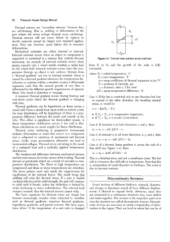
supported or contained in a manner that restricts thermal Figure 1-4. Thermal linear gradient across shell wall.
movement. An example of external restraint occurs when
piping expands into a vessel nozzle creating a radial load from TI to Tz and the growth of the cube is fully
on the vessel shell. Internal restraint occurs when the tem- restrained:
perature through an object is not uniform. Stresses from
a “thermal gradient” are due to internal restraint. Stress is where T1= initial temperature, O F
caused by a thermal gradient whenever the temperature dis- Tz = new temperature, OF
(11 = mean coefficient of thermal expansion in./in./”F
tribution or variation within a member creates a differential E = modulus of elasticity, psi
expansion such that the natural growth of one fiber is v = Poisson’s ratio = .3 for steel
influenced by the different growth requirements of adjacent
fibers. The result is distortion or warpage. AT = mean temperature difference, OF
A transient thermal gradient occurs during heat-up and Case 1: If the bar is restricted only in one direction but free
cool-down cycles where the thermal gradient is changing to expand in the other drection, the resulting uniaxial
with time. stress, 0, would be
Thermal gradients can be logarithmic or linear across a
vessel wall. Given a steady heat input inside or outside a tube 0 = -Ea(Tz - TI)
the heat distribution will be logarithmic if there is a tem- 0 If Tt > TI, 0 is compressive (expansion).
perature difference between the inside and outside of the 0 If TI > Tz, 0 is tensile (contraction).
tube. This effect is significant for thick-walled vessels. A
linear temperature distribution occurs if the wall is thin. Case 2: If restraint is in both directions, x and y, then:
Stress calculations are much simpler for linear distribution.
Thermal stress ratcheting is progressive incremental 0, = cy = -(~IE AT/1- o
inelastic deformation or strain that occurs in a component Case 3: If restraint is in all three directions, x, y, and z, then
that is subjected to variations of mechanical and thermal
stress. Cyclic strain accumulation ultimately can lead to 0, = oy = 0, = -aE AT11 - 2~
incremental collapse. Thermal stress ratcheting is the result Case 4: If a thermal linear gradient is across the wall of a
of a sustained load and a cyclically applied temperature thin shell (see Figure 14), then:
distribution.
The fundamental difference between mechanical stresses 0, = O+ = f(11E AT/2(1- V)
and thermal stresses lies in the nature of the loading. Thermal This is a bending stress and not a membrane stress. The hot
stresses as previously stated are a result of restraint or tem- side is in tension, the cold side in compression. Note that this
perature distribution. The fibers at high temperature are is independent of vessel diameter or thickness. The stress is
compressed and those at lower temperatures are stretched. due to internal restraint.
The stress pattern must only satisfy the requirements for
equilibrium of the internal forces. The result being that
yielding will relax the thermal stress. If a part is loaded Discontinuity Stresses
mechanically beyond its yield strength, the part will continue
to yield until it breaks, unless the deflection is limited by Vessel sections of different thickness, material, dameter,
strain hardening or stress redistribution. The external load and change in directions would all have different displace-
remains constant, thus the internal stresses cannot relax. ments if allowed to expand freely. However, since they
The basic equations for thermal stress are simple but are connected in a continuous structure, they must deflect
become increasingly complex when subjected to variables and rotate together. The stresses in the respective parts at or
such as thermal gradents, transient thermal gradients, near the juncture are called discontinuity stresses. Disconti-
logarithmic gradients, and partial restraint. The basic equa- nuity stresses are necessary to satisfy compatibility of defor-
tions follow. If the temperature of a unit cube is changed mation in the region. They are local in extent but can be of