Page 291 - Pressure Swing Adsorption
P. 291

:  .i.l
                                                                                     I
                                                                                     '        EXTENSIONS  OF THE PSA  CONCEPT                             269
             268                                   PRESSURE SWING ADSORPTION
                                                                                              gas phase ( y ).
             conventional. PSA system  1s  somewhat  remote,  since  independent control of
                                                                                                   dq*   RT  da*
             pressure and flow.  which  is  a  key  feature of the parametnc pump, 1s  lacking                                                           (7.4)
             in  PSA.  A  true pressure swing  parametric pump has,  however,  been demon•         de  - P   dy
             strated by  Keller and Kuo,'  who called their process the molecular gate.  The   Thus at high pressure da* /de  is  relatively smaller and  we  1s  correspondingly
             essentiai components of such a system are shown schematically in  Figure 7.2.    larger. The anaiogy between the thermal parametnc ,pump dnven by temper-
             The  pistons.  which  are  of  unequal  displacement,  are  coupled  so  that  a   ature  vanation  and  the  gas-phase  system  driven  by  a  pressure  variation  ,s
             constant  phase  angle  1s  mamtamed.  The  synchronized  movement  of  the      therefore clear.
             pistons  is  adjusted  so  that  the  gas  flows  upwards  through  the  bed  at  high   The  maximum vanation  m  the  volume  between  the  01stons  occurs  when
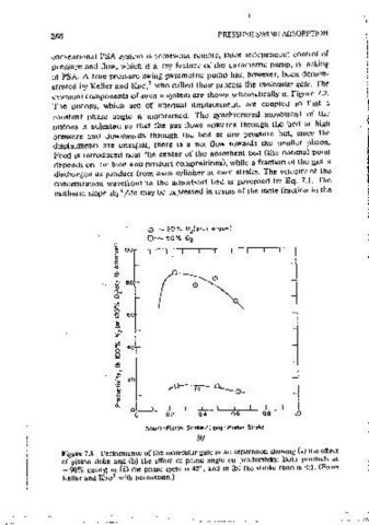
             Pressure  and  downwards  through  the  bed  at  low  pressure  but,  smce  the   the  difference  m  phase  angle  is  45°  If kinetic  effects  are  unimportant  this
             displacments  are  unequal,  there  is  a  net  flow  towards  the  smaller- piston.   condition should  give  the  maximum variation  in  pressure and therefore  the
             Fe~d  is  Introduced  near the center of the adsorbent  bed (the optimal point   best performance. For air separatidn over a  zeolite adsorbent the separatron
             ctepencts on  the feed and oroctuct compositions), while a fraction of the gas 1s   factor (aN /Oi)  IS  about 3.5.  Assuming linear isotherms,  this  means  that  the
             discharged as product from  each cylinder at each stroke. The velocity of the    capacity of the bed  1s  about three and oncwhalf times as great for  nitrogen as
             concentration  wavefront  m  the  adsorbent  bed  ls  governed  by  Eo.  7.1.  The   I   for  oxygen.  For  any  given  pressure  change  the  ratio  of  the  nitrogen  and
              1 sotherm siope dq* /de may be expressed in  terms of the mole fraction  m the   oxygen  voJumes  reomred  to  oressunze  the  bed  muSt  lie  m  this  ratio.  The
                                                                                              expenmental data,  shown  m Figure 7.3,  are  m  approximate accordance with
                                                                                     l
                                                                                     l
                                   0·...._.9Qo/.,  N (plus  or9on)
                                            2                                                                  0· -90°1.  N;z(p1t,,  orqon)
                                   0~- 90•1.,  Oz                                                      I-      0·-90¾ Oz
                           c                                                                           z
                                                                                                       w
                           •  100
                           i'                                                        I                 ill  100
                           ~                                                                           ~
                           ~
                           <t                                                                          0
                                                                                                       "'
                                                  0
                           ~
                           "  80
                                                                                                       ~
                           0                 0                                                         "  80
                                                                                                       0
                           J!N                                                                         ~
                           0         I                                                                 ;;N
                           "                                                                           ;J
                           •
                           ~  60                                                                       8  60
                           i                                                                           .!!
                            N                                                                                                                 \
                           z                                                                           z  N                                    '
                           ~   •o                                                                      ~            I
                           8                                                                              •o        I  I                        \
                                                                                                       ,.:
                           "                                                                           "           I
                                                                                                       I-
                            ~
                           :E   20                                                                     >                                          I
                                                                                                       ;:
                           u  ,        ~                                                               u   20
                                                                                                       ::,
                           'O                                                                          0
                            e
                                                                                                       0
                           a.                                                                          "'  ..
                               0
                                0      0.2    04      06     0.8    lO                                     0
                                                                                                            60'    :w      o·     :w     60'
                                  Shor! •Pis1on  Stroke /Lon9 · PiS1on  Stfl>M
                                                                                                                Log                 Leod
                                              /a)
                                                                                                                PHASE  ANGLE,SHORT  VS  LONG  PISTON
               Figure 7.3  Performance of the mo1ecuiar gate m atr separation showmg (a) the effect
               of piston  stoke  and  (b)  the  effect of phase  angle  on  productivity.  Both  products  at                (b)
               ~ 90% purity;  m (a) the phase cycle  1s  45°. and in  (b)  the stroke ratio 1s  4: 1.  (From
                                                                                                                     Figure 7.3  (Contmued).
                           3
               Keller and Kuo with  oerm1ss1on.)
   286   287   288   289   290   291   292   293   294   295   296