
Page 220 - Principles and Applications of NanoMEMS Physics
P. 220
5. NANOMEMS APPLICATIONS: PHOTONICS 209
Here an opaque screen containing an aperture of dimension much smaller
than the optical wavelength is interposed in the light path, in front the
sample surface, thus circumscribing the passing light to diffract from this
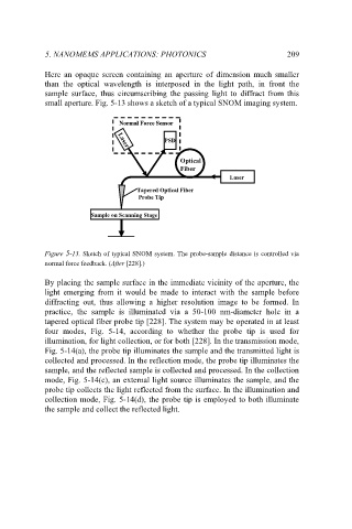
small aperture. Fig. 5-13 shows a sketch of a typical SNOM imaging system.
Normal Force Sensor
Normal Force Sensor
Normal Force Sensor
PSD
PSD
PSD
Laser
Laser
Laser
Optical
Optical
Optical
Fiber
Fiber
Fiber
Laser
Laser
Laser
Tapered Optical Fiber
Tapered Optical Fiber
Probe Tip
Probe Tip
Sample on Scanning Stage
Sample on Scanning Stage
Sample on Scanning Stage
Figure 5-13. Sketch of typical SNOM system. The probe-sample distance is controlled via
normal force feedback. (After [228].)
By placing the sample surface in the immediate vicinity of the aperture, the
light emerging from it would be made to interact with the sample before
diffracting out, thus allowing a higher resolution image to be formed. In
practice, the sample is illuminated via a 50-100 nm-diameter hole in a
tapered optical fiber probe tip [228]. The system may be operated in at least
four modes, Fig. 5-14, according to whether the probe tip is used for
illumination, for light collection, or for both [228]. In the transmission mode,
Fig. 5-14(a), the probe tip illuminates the sample and the transmitted light is
collected and processed. In the reflection mode, the probe tip illuminates the
sample, and the reflected sample is collected and processed. In the collection
mode, Fig. 5-14(c), an external light source illuminates the sample, and the
probe tip collects the light reflected from the surface. In the illumination and
collection mode, Fig. 5-14(d), the probe tip is employed to both illuminate
the sample and collect the reflected light.