
Page 175 - Principles of Applied Reservoir Simulation 2E
P. 175
160 Principles of Applied Reservoir Simulation
nature when vertical flow is rapid relative to horizontal flow. This situation
occurs when the vertical permeability of the reservoir is comparable in
magnitude to its horizontal permeability, and when density differences are
significant, such as in gas-oil or gas-water systems. For more discussion of
specific pseudoization techniques, see Taggart, et al. [ 1995] and their references,
One reason for the continuing popularity of 2D grids is that the expecta-
tion of what is appropriate grid resolution has changed as simulation technology
evolved. Thus, even though 3D models could be used today with the grid
resolution that was considered acceptable a decade ago for 2D models, modern
expectations often require that even finer grids be used for the same types of
problems. This is an example of a task expanding to fit the available resources.
It is not obvious that increased grid definition is leading to better reservoir
management decisions. Indeed, it can be argued that the technological ability
to add complexity is making it more difficult for people to develop a "big
picture" understanding of the system being studied because they are too busy
focusing on the details of a complex model. Once again, a judicious use of
Ockham's Razor is advisable in selecting a reservoir grid. The grid should be
appropriate for achieving study objectives.
Near-wellbore coning models may be either 2D or 3D grids, but are
defined in cylindrical rather than Cartesian coordinates. Coning (or radial)
models are designed to study rapid pressure and saturation changes. An example
of a radial grid is shown in Figure 16-8. High throughput, that is, large flow rate
through relatively small, near-wellbore gridblocks is most effectively simulated
by a fully implicit formulation. IMPES
can be used to model coning, but timesteps
must be very small, possibly on the order
of minutes or hours. Small timesteps are
not a problem if the duration of the mod-
eled history is short, as it would be in the
case of a pressure transient test. O Corner Point
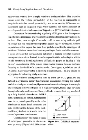
Gridblocks may be defined in terms • Block Centered
of comer-point geometry or block-cen- Figure 16-4. Gridblock represen-
tered geometry (Figure 16-4). Block-cen- tation.