
Page 176 - Principles of Applied Reservoir Simulation 2E
P. 176
Part II: Reservoir Simulation 161
tered geometry is the most straight forward technique, but comer-point geometry
has gained popularity because it yields more visually realistic representations
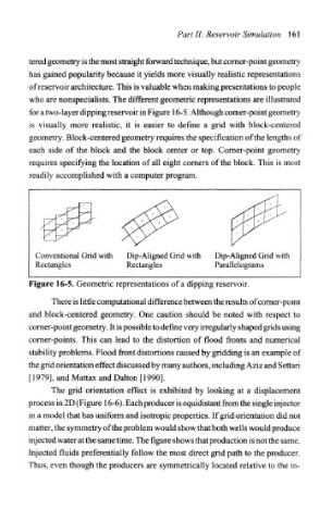
of reservoir architecture. This is valuable when making presentations to people
who are nonspecialists. The different geometric representations are illustrated
for a two-layer dipping reservoir in Figure 16-5. Although corner-point geometry
is visually more realistic, it is easier to define a grid with block-centered
geometry. Block-centered geometry requires the specification of the lengths of
each side of the block and the block center or top. Corner-point geometry
requires specifying the location of all eight corners of the block. This is most
readily accomplished with a computer program.
Conventional Grid with Dip-Aligned Grid with Dip-Aligned Grid with
Rectangles Rectangles Parallelograms
Figure 16-5. Geometric representations of a dipping reservoir.
There is little computational difference between the results of corner-point
and block-centered geometry. One caution should be noted with respect to
comer-point geometry. It is possible to define very irregularly shaped grids using
corner-points. This can lead to the distortion of flood fronts and numerical
stability problems. Flood front distortions caused by gridding is an example of
the grid orientation effect discussed by many authors, including Aziz and Settari
[1979], and Mattax and Dalton [1990].
The grid orientation effect is exhibited by looking at a displacement
process in 2D (Figure 16-6). Each producer is equidistant from the single injector
in a model that has uniform and isotropic properties. If grid orientation did not
matter, the symmetry of the problem would show that both wells would produce
injected water at the same time. The figure shows that production is not the same.
Injected fluids preferentially follow the most direct grid path to the producer.
Thus, even though the producers are symmetrically located relative to the in-