
Page 186 - Principles of Applied Reservoir Simulation 2E
P. 186
Part II: Reservoir Simulation 171
Peaceman showed that the shut in pressure P ws of an actual well equals
the simulator well block pressure P 0 at a shut in time A/ 5 given by
(17.1)
f
K
where K is permeability, <f) is porosity, |l is viscosity, and C T is total compress-
ibility. Units for all variables are given in Table 17-2 at the end of this section,
Log (T;, + AO/A/
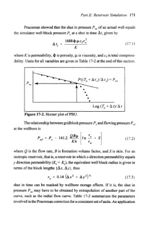
Figure 17-2. Horner plot of PBU.
The relationship between gridblock pressure P 0 and flowing pressure P wf
at the wellbore is
P..., = P. - 141.2 In — + S (17,2)
r.
where Q is the flow rate, B is formation volume factor, and S is skin. For an
isotropic reservoir, that is, a reservoir in which x-direction permeability equals
= K y), the equivalent well block radius is given in
y direction permeability (K x
terms of the block lengths {A*, Ay}, thus
2 2 /2
= 0.14 (A* + A>> )' (17.3)
r o
shut in time can be masked by wellbore storage effects. If it is, the shut in
pressure P^ may have to be obtained by extrapolation of another part of the
curve, such as the radial flow curve. Table 17-2 summarizes the parameters
involved in the Peaceman correction for a consistent set of units. An application