
Page 137 - Process Equipment and Plant Design Principles and Practices by Subhabrata Ray Gargi Das
P. 137
134 Chapter 5 Heat exchanger network analysis
5.4.4 Grid diagram
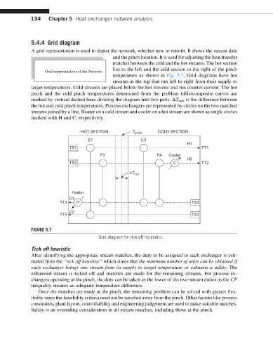
A grid representation is used to depict the network, whether new or retrofit. It shows the stream data
and the pinch location. It is used for adjusting the heat transfer
matches between the cold and the hot streams. The hot section
lies to the left and the cold section to the right of the pinch
Grid representation of the Network
temperature as shown in Fig. 5.7. Grid diagrams have hot
streams at the top that run left to right from their supply to
target temperatures. Cold streams are placed below the hot streams and run counter-current. The hot
pinch and the cold pinch temperatures determined from the problem table/composite curves are
marked by vertical dashed lines dividing the diagram into two parts. DT min is the difference between
the hot and cold pinch temperatures. Process exchangers are represented by circles on the two matched
streams joined by a line. Heater on a cold stream and cooler on a hot stream are shown as single circles
marked with H and C, respectively.
HOT SECTION T pinch COLD SECTION
E1 E3
H1
TS1 TT1
E2 E4 Cooler
H2
TS2 C TT2
ΔT min
Heater
C1
TT3 H TS3
C2
TT4 TS4
FIGURE 5.7
Grid diagram for tick off heuristics.
Tick off heuristic
After identifying the appropriate stream matches, the duty to be assigned to each exchanger is esti-
mated from the “tick off heuristic” which states that the minimum number of units can be obtained if
each exchanger brings one stream from its supply to target temperature or exhausts a utility. The
exhausted stream is ticked off and matches are made for the remaining streams. For process ex-
changers operating at the pinch, the duty can be taken as the lower of the two-stream duties as the CP
inequality ensures an adequate temperature difference.
Once the matches are made at the pinch, the remaining problem can be solved with greater flex-
ibility since the feasibility criteria need not be satisfied away from the pinch. Other factors like process
constraints, plant layout, controllability and engineering judgement are used to make suitable matches.
Safety is an overriding consideration in all stream matches, including those at the pinch.