
Page 141 - Process Equipment and Plant Design Principles and Practices by Subhabrata Ray Gargi Das
P. 141
138 Chapter 5 Heat exchanger network analysis
(A) (B)
HP
HP
steam steam
Hot
composite
curve
LP
T T steam
Hot Cold composite
Cold composite ΔT min curve
composite curve ΔT min
curve
CW CW
H H
(C) (D)
HP HP
steam steam
*
T LP LP steam Utility pinch
Grand composite
curve Grand composite
T * T * curve
Process pinch
*
T cw Utility pinch
Refrigeration CW
Refrigeration
Δ H * Δ H *
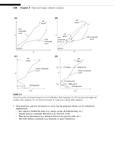
FIGURE 5.9
Using Composite and Grand Composite Curve for Multiple Utility Targeting: (A), (B) Composite for single and
multiple utility targeting; (C), (D) Grand Composite for single and multiple utility targeting.
• General process and site information to verify that the proposed scheme can be realistically
implemented.
- Key objective behind the study (e.g. energy saving, de-bottlenecking, etc.)
- Specific process constraints that need to be observed, if any
- Plant layout information (e.g. distances between key process units, etc.)
- Site-wide utilities constraints (e.g. hardware or space limitations)