
Page 189 - Process Equipment and Plant Design Principles and Practices by Subhabrata Ray Gargi Das
P. 189
6.6 Evaporator design 187
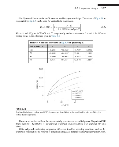
Usually overall heat transfer coefficients are used in evaporator design. The curves of Fig. 6.18 as
represented by Eq. 6.7 can be used for vertical tube evaporators.
" #
ða bÞ
U ¼ 5:6783 b þ (6.7)
d
1 þð0:5556 DT eff =cÞ
2
o
Where U and DT eff are in W/m K and C, respectively, and the constants a, b, c and d for different
boiling points in the effect are given in Table 6.4.
Table 6.4 Constants to be used in Eq. 6.7 for predicting U.
Boiling Point ( C) a b c d
100 0.4530 720.2609 12.7327 0.9524
75 0.4856 684.4337 22.3611 1.1038
60 0.2090 509.0018 26.5472 1.2798
50 0.3641 687.8854 83.2172 1.0207
3000
2000
U (W/m 2 k) 1000
BP 100°C
BP 75°C
0 BP 60°C
BP 50°C
0 20 40
(°C)
ΔT eff
FIGURE 6.18
Relationship between boiling point (BP), temperature drop (DT eff ) and overall heat transfer coefficient in
vertical tube evaporators.
These curves are derived from the experimentally generated curves by Badger and Shepard (AIChE
00
00
00
Trans. 13(I):101e137(1920)) for 30 diameter evaporator with 24 numbers of 2 diameter 48 long
tubes.
While DT eff and condensing temperature (T con ) are fixed by operating conditions and not by
evaporator construction, the removal of noncondensable gases depends on the evaporator construction.