
Page 210 - Process Equipment and Plant Design Principles and Practices by Subhabrata Ray Gargi Das
P. 210
208 Chapter 7 Industrial cooling systems
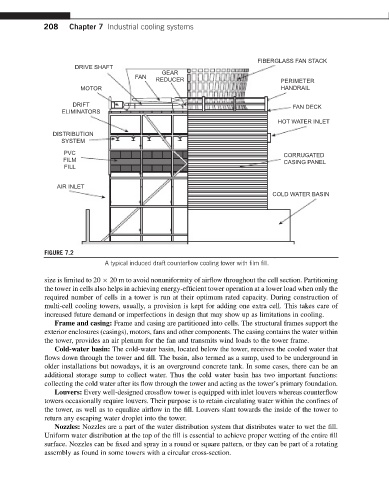
FIBERGLASS FAN STACK
DRIVE SHAFT
GEAR
FAN
REDUCER PERIMETER
MOTOR HANDRAIL
DRIFT FAN DECK
ELIMINATORS
HOT WATER INLET
DISTRIBUTION
SYSTEM
PVC CORRUGATED
FILM
CASING PANEL
FILL
AIR INLET
COLD WATER BASIN
FIGURE 7.2
A typical induced draft counterflow cooling tower with film fill.
size is limited to 20 20 m to avoid nonuniformity of airflow throughout the cell section. Partitioning
the tower in cells also helps in achieving energy-efficient tower operation at a lower load when only the
required number of cells in a tower is run at their optimum rated capacity. During construction of
multi-cell cooling towers, usually, a provision is kept for adding one extra cell. This takes care of
increased future demand or imperfections in design that may show up as limitations in cooling.
Frame and casing: Frame and casing are partitioned into cells. The structural frames support the
exterior enclosures (casings), motors, fans and other components. The casing contains the water within
the tower, provides an air plenum for the fan and transmits wind loads to the tower frame.
Cold-water basin: The cold-water basin, located below the tower, receives the cooled water that
flows down through the tower and fill. The basin, also termed as a sump, used to be underground in
older installations but nowadays, it is an overground concrete tank. In some cases, there can be an
additional storage sump to collect water. Thus the cold water basin has two important functions:
collecting the cold water after its flow through the tower and acting as the tower’s primary foundation.
Louvers: Every well-designed crossflow tower is equipped with inlet louvers whereas counterflow
towers occasionally require louvers. Their purpose is to retain circulating water within the confines of
the tower, as well as to equalize airflow in the fill. Louvers slant towards the inside of the tower to
return any escaping water droplet into the tower.
Nozzles: Nozzles are a part of the water distribution system that distributes water to wet the fill.
Uniform water distribution at the top of the fill is essential to achieve proper wetting of the entire fill
surface. Nozzles can be fixed and spray in a round or square pattern, or they can be part of a rotating
assembly as found in some towers with a circular cross-section.