
Page 215 - Process Equipment and Plant Design Principles and Practices by Subhabrata Ray Gargi Das
P. 215
7.2 Cooling tower 213
Cooling towers have certain design values, but the best cooling tower effectiveness requires
adjustment for seasonal variations and tuning of water and air flow rates. Adjustments can be made by
water box loading changes or blade angle adjustments.
7.2.4 Cooling water circuit in a process plant
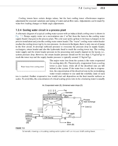
A schematic diagram of a typical cooling water system with an induced draft cooling tower is shown in
3
Fig. 7.5. Pumps supply water (at a recirculation rate C m /hr) from the basin to the cooling water
supply header that goes to the process plant. The cold water picks up heat in the heat exchangers in the
process installation and joins the cooling water return header. The “warm” cooling water return header
reaches the cooling tower top by its own pressure. As shown in the figure, there is only one set of pump
in the flow circuit. It develops sufficient pressure to overcome the pressure drop in supply header,
exchangers, return header and also the hydrostatic head to reach the cooling tower top. The cooling
water supply and the return header pressure in the processing unit usually depend on the layout, i.e.,
2
system pressure drop. However, the return header pressure should not be less than 1.5 kg/cm (g) to
2
reach the tower top and the supply header pressure is typically around 3.5 kg/cm (g).
The major water loss from the system is the water evaporated
for cooling duty (E). Theoretically, evaporation from a cooling
tower is pure water, while all of the dissolved ions are left
Water losses from cooling tower
behind in the system. If the water loss is only due to evapora-
tion, the concentration of the dissolved ions in the recirculating
water would continue to rise until the solubility limit of each
ion is reached. Further evaporative loss would start salt deposition on the heat transfer surfaces as
scales. To avoid this, the concentration of critical scaling-prone ions in the circulating water is usually
FIGURE 7.5
Schematic showing a circulating cooling water system with an induced draft cooling tower.