
Page 211 - Process Equipment and Plant Design Principles and Practices by Subhabrata Ray Gargi Das
P. 211
7.2 Cooling tower 209
Air inlet: It is the area of air entry into the tower. This may take up an entire side of a tower for
crossflow design or be located low on the side or the bottom of the tower in counterflow design.
Fans: Cooling tower fans must move large volumes of air efficiently and with minimum vibration.
Generally, propeller fans are used in induced draft towers and both propeller and centrifugal fans are
found in forced draft towers. Propeller fans have ability to move vast quantities of air at the relatively
low static pressure encountered. They are comparatively inexpensive, may be used on tower of any size
and can develop high overall efficiencies. Compared to propeller fans, the centrifugal fans can work
against higher head load and are usually used in cooling towers designed for indoor installations.
However, their inability to handle large volumes of air and high input horsepower requirement limits
their use to relatively small applications. Airflow in propeller fans can be adjusted by varying the blade
pitch and RPM in order to provide the required airflow with minimum input fan power. The optimum
speed of a cooling tower fan seldom coincides with the most efficient speed of its motor and a gear
reducer is often installed between the motor and the fan.
Drift eliminators: Drift eliminators remove entrained water from the exiting air by forcing it to
undergo sudden changes in direction. The centrifugal force separates the water drops as these hit the
surface. The collected water is returned to the tower.
Fill: Most towers employ fills (made of plastic or wood) to facilitate heat transfer. Fill is used to
increase contact area, as well as turbulence that promotes intimate vaporeliquid contacting. This
determines the efficiency of the tower. An efficiently designed fill media with appropriate water
distribution, drift eliminator, fan, gearbox and motor results in lower fan power consumption as the
airflow requirement is lowered.
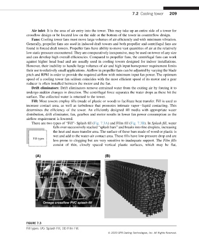
There are two types of “Fill”- Splash fill (Fig. 7.3A) and Film fill (Fig. 7.3B). In Splash fill, water
falls over successively stacked “splash bars” and breaks into fine droplets, increasing
the heat and mass transfer area. The surface of these bars made of wood or plastic is
wet and add to the water-air contact area. These fills have low-pressure drop and are
Fill types
less prone to clogging but are very sensitive to inadequate support. The Film fills
consist of thin, closely spaced vertical plastic surfaces, which may be flat,
FIGURE 7.3
Fill types: (A): Splash Fill, (B) Film Fill.
© 2020 SPX Cooling Technologies, Inc. All Rights Reserved.