
Page 256 - Process Equipment and Plant Design Principles and Practices by Subhabrata Ray Gargi Das
P. 256
10.2 Tray column 257
10.2 Tray column
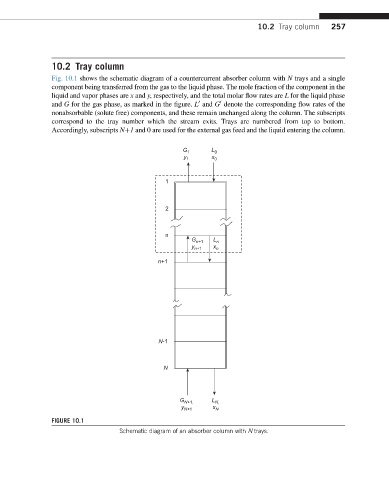
Fig. 10.1 shows the schematic diagram of a countercurrent absorber column with N trays and a single
component being transferred from the gas to the liquid phase. The mole fraction of the component in the
liquid and vapor phases are x and y, respectively, and the total molar flow rates are L for the liquid phase
and G for the gas phase, as marked in the figure. L and G denote the corresponding flow rates of the
0
0
nonabsorbable (solute free) components, and these remain unchanged along the column. The subscripts
correspond to the tray number which the stream exits. Trays are numbered from top to bottom.
Accordingly, subscripts Nþ1 and 0 are used for the external gas feed and the liquid entering the column.
G 1 L 0
y 1 x 0
1
2
n
G n+1 L n
y n+1 x n
n+1
N-1
N
L
G N+1, N,
y N+1 x N
FIGURE 10.1
Schematic diagram of an absorber column with N trays.