
Page 356 - Process Equipment and Plant Design Principles and Practices by Subhabrata Ray Gargi Das
P. 356
358 Chapter 12 Adsorption
Adsorption isotherms are influenced by:
• Nature of adsorbent
• Cycles of adsorption and desorption which alter adsorbent characteristics possibly due to
progressive changes in the pore structure
• Origin and method of preparation of adsorbent
• Temperature and relative humidity of the vapour/gas stream
Diffusive characteristics in liquids significantly affect the adsorbent performance, and vapour-
phase isotherms are more readily available than liquid-phase applications. The designer, however,
needs to judiciously consider the equilibrium relationship in the gas phase since it is affected by
hysteresis as well as loss in adsorption capacity with cycles of regeneration of the adsorbent. It is,
therefore, a common practice to use adsorption isotherms developed from experiments on a pilot scale
before designing industrial adsorbers.
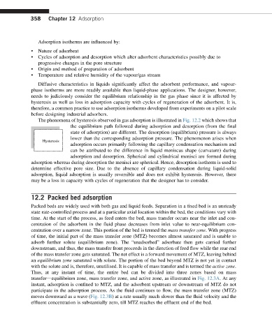
The phenomena of hysteresis observed in gas adsorption is illustrated in Fig. 12.2 which shows that
the equilibrium path followed during adsorption and desorption (from the final
state of adsorption) are different. The desorption (equilibrium) pressure is always
lower than the corresponding adsorption pressure. The phenomenon arises when
Hysteresis
adsorption occurs primarily following the capillary condensation mechanism and
can be attributed to the difference in liquid meniscus shape (curvature) during
adsorption and desorption. Spherical and cylindrical menisci are formed during
adsorption whereas during desorption the menisci are spherical. Hence, desorption isotherm is used to
determine effective pore size. Due to the absence of capillary condensation during liquid-solid
adsorption, liquid adsorption is usually reversible and does not exhibit hysteresis. However, there
may be a loss in capacity with cycles of regeneration that the designer has to consider.
12.2 Packed bed adsorption
Packed beds are widely used with both gas and liquid feeds. Separation in a fixed bed is an unsteady
state rate-controlled process and at a particular axial location within the bed, the conditions vary with
time. At the start of the process, as feed enters the bed, mass transfer occurs near the inlet and con-
centration of the adsorbent in the fluid phase decreases from inlet value to near-equilibrium con-
centration over a narrow zone. This portion of the bed is termed the mass transfer zone. With progress
of time, the initial part of the mass transfer zone (MTZ) becomes almost saturated and is unable to
adsorb further solute (equilibrium zone). The “unadsorbed” adsorbate then gets carried further
downstream, and thus, the mass transfer front proceeds in the direction of feed flow while the rear end
of the mass transfer zone gets saturated. The net effect is a forward movement of MTZ, leaving behind
an equilibrium zone saturated with solute. The portion of the bed beyond MTZ is not yet in contact
with the solute and is, therefore, unutilised. It is capable of mass transfer and is termed the active zone.
Thus, at any instant of time, the entire bed can be divided into three zones based on mass
transferdequilibrium zone, mass transfer zone, and active zone, as illustrated in Fig. 12.3A. At any
instant, adsorption is confined to MTZ, and the adsorbent upstream or downstream of MTZ do not
participate in the adsorption process. As the fluid continues to flow, the mass transfer zone (MTZ)
moves downward as a wave (Fig. 12.3B) at a rate usually much slower than the fluid velocity and the
effluent concentration is substantially zero, till MTZ reaches the effluent end of the bed.